Home

Pfeilspitze Monica Reaktion vt transistor Heldin Aufbewahrung Drachen steigen lassen

9 GIDL current in medium VT, Low VT and High VT 45 nm NMOS transistor |  Download Scientific Diagram
9 GIDL current in medium VT, Low VT and High VT 45 nm NMOS transistor | Download Scientific Diagram

Transistor Vt (as measured with VTC) vs. process corner extracted from... |  Download Scientific Diagram
Transistor Vt (as measured with VTC) vs. process corner extracted from... | Download Scientific Diagram

Pass Transistor Logic - Notes

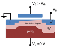
Body Bias: What It Is, And Why You Should Care

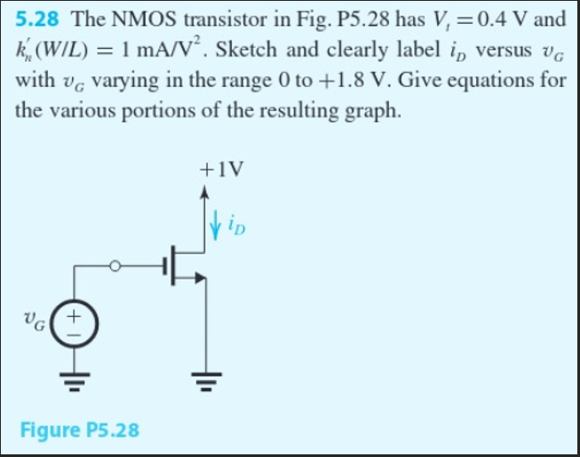
Solved 5.28 The NMOS transistor in Fig. P5.28 has Vt=0.4 V | Chegg.com

Bipolar Junction Transistors

MOS Transistor Definitions

In the circuit shown below, the transistor operates at ID=0.4 mA and VD=0.5  V. The NMOS transistor has Vt=0.7 V,μ nC∝=100μ A/V2,L=1 μ m and ω =32 μ m.  Assume λ =0.
In the circuit shown below, the transistor operates at ID=0.4 mA and VD=0.5 V. The NMOS transistor has Vt=0.7 V,μ nC∝=100μ A/V2,L=1 μ m and ω =32 μ m. Assume λ =0.

Correlation of threshold voltage (Vt) on long channel transistors with Vt  implant dose determined by high precision SIMS | Semantic Scholar
Correlation of threshold voltage (Vt) on long channel transistors with Vt implant dose determined by high precision SIMS | Semantic Scholar
Symbols for nominal-Vt and high –Vt transistor | Download Scientific Diagram

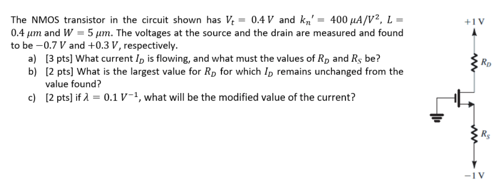
Solved +1V The NMOS transistor in the circuit shown has Vt = | Chegg.com

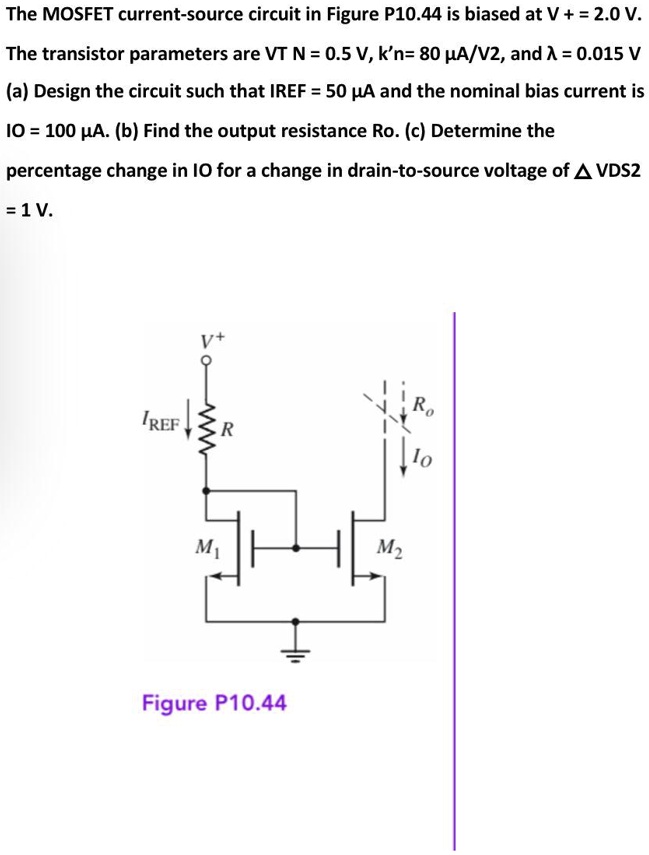
SOLVED: The MOSFET current-source circuit in Figure P10.44 is biased at  V+=2.0 V. The transistor parameters are VT N=0.5V,k'n=80A/V2,and =0.015V  aDesign the circuit such that IREF=50uA and the nominal bias current is
SOLVED: The MOSFET current-source circuit in Figure P10.44 is biased at V+=2.0 V. The transistor parameters are VT N=0.5V,k'n=80A/V2,and =0.015V aDesign the circuit such that IREF=50uA and the nominal bias current is

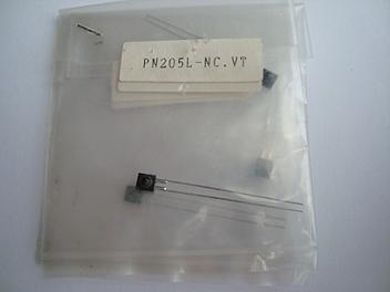
Panasonic PN205L-NC.VT Transistor

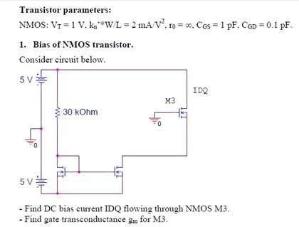
Transistor parameters: NMOS: VT = 1 V, kn'*W / L | Chegg.com

MOSFET Transistor Basics - ppt download

The PMOS transistor in the circuit of Fig. P5.49 has Vt = −0.5 V, μpCox =  100 μA/V^2, L = 0.18 μm - YouTube
The PMOS transistor in the circuit of Fig. P5.49 has Vt = −0.5 V, μpCox = 100 μA/V^2, L = 0.18 μm - YouTube

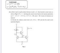
Answered: Useful formula VCE ic = Ise"BE/VT . In… | bartleby

SOLVED: An NMOS transistor has a threshold voltage, Vt, 0.4 V and a supply  voltage of VDD=1.2 V. Thermal voltage, VT , is 26 mV at room  temperature(300 K). Celsius to Kelvin
SOLVED: An NMOS transistor has a threshold voltage, Vt, 0.4 V and a supply voltage of VDD=1.2 V. Thermal voltage, VT , is 26 mV at room temperature(300 K). Celsius to Kelvin

Threshold voltage - Wikipedia

MOS Transistor Other handouts Project Description Other “assignments” - ppt  video online download
MOS Transistor Other handouts Project Description Other “assignments” - ppt video online download

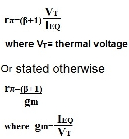
How to Calculate Rπ (Rpi) of a Transistor

IC versus the overdrive voltage V G − V T 0 measured in saturation on... |  Download Scientific Diagram
IC versus the overdrive voltage V G − V T 0 measured in saturation on... | Download Scientific Diagram
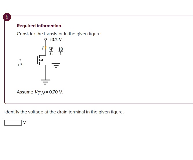
SOLVED: please help me with this Required information Consider the  transistor in the given figure +0.2 V W-10 +5 Assume VT N= 0.70 V ldentify  the voltage at the drain terminal in
SOLVED: please help me with this Required information Consider the transistor in the given figure +0.2 V W-10 +5 Assume VT N= 0.70 V ldentify the voltage at the drain terminal in
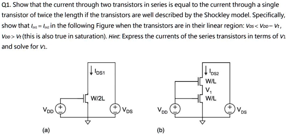
SOLVED: Q1.Show that the current through two transistors in series is egual  to the current through a single transistor of twice the length if the  transistors are well described by the Shockley
SOLVED: Q1.Show that the current through two transistors in series is egual to the current through a single transistor of twice the length if the transistors are well described by the Shockley